

implementation
Baxter vs Sawyer
The robot we used for this project was Sawyer. We did a lot of our testing with Baxter, but we decided to use Sawyer as our final artist because of his dexterity. If we were to continue working on this project, we’d preferably take a picture of the muse with one of Sawyer’s cameras. We could also use Sawyer’s arm camera to compare what we’ve drawn to the original image to make it even closer to reality.
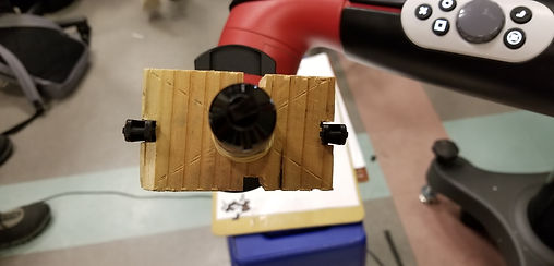
Pen Holder
Holding things is hard. (See: Ross Bowers during the Big Game 2017.) But holding things can be even harder for robots than it is for humans. This way we could slide Sawyer’s grippers into the notches. That way, there was no room for slipping or rotation.
We also tried different sized holes for the pen: ¾ inch and ⅞ inch. We ultimately used the ⅞ inch and used rubber bands as bushings. In theory, this would accommodate if Sawyer pressed too hard on the page with the pen. If that happened, the pen would move up in the holder, preventing too much damage to the tip. However, in practice, we didn’t notice much of a difference between the holders.
The software of the finished product had four major consecutive stages: image processing, path planning, Sawyer calibration, and path execution.
Path Planning
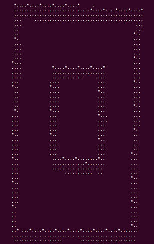
The input to this stage is a binary matrix of dimensions approximately 100x140. The goal is to find a collection of curves (each defined by a series of coordinates in this 100x140 matrix) such that the Sawyer arm moving a pen across the canvas according to these curves would recreate the line drawing. We did not use the Canny algorithm to find these curves because each line corresponds to two edges. Depending on the complexity of the image it is not always clear which two edges correspond to the same line, so an edge merging process is imperfect. Instead, we opted for a simpler greedy algorithm. We treat the input binary matrix as a boolean matrix where each entry indicates whether we have "visited" that particular pixel in our recreation line drawing. All of the entries which are initially 0/false have already been "visited" because we don't want a pen mark there in the final drawing. We scan the binary matrix for an entry that has not been visited yet. The coordinates of that point serve as the starting point of our new curve. We mark that pixel and the pixels in an arbitrary block around it (3x3 in our case) as visited, and then check adjacent pixels to see if any have yet to be visited. If such a pixel exists, then we add its coordinates to the in-progress curve and perform the same visiting process starting from this new point (marking the chunk as visited, looking for unvisited adjacent pixels, and repeating). When we can no longer find any unvisited adjacent pixels, then we check to see if the last point we have added is close to the first point. If it is, then we re-add the first point to the end of the curve, as this curve is likely a closed loop. This algorithm is fairly crude and has much room for improvement, but it served our purposes quite well.
Sawyer Calibration
In order to draw the curves, we need to map the coordinates from our binary matrix (range of 100x140) to 3D coordinates of the destination canvas in the real-world space defined around Sawyer. We positioned our canvas on a horizontal plane in front of Sawyer, and then physically moved the arm to the top-left and bottom-right corners of the canvas, recording the coordinates of these two points. Since we assumed that the canvas was perfectly horizontal, we averaged the Z-coordinates of these two points in order to define the horizontal plane of the destination space. Then, using the two pairs of X and Y coordinates as boundary points, we mapped each binary matrix coordinate to its respective real world coordinate (including the Z-coordinate calculated earlier).
Path Execution
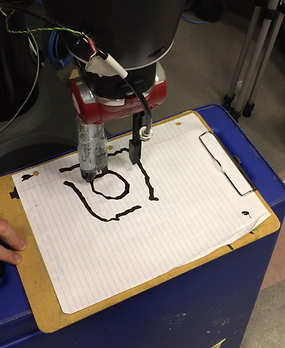
The goal of this stage is to move Sawyer's arm (and attached pen!) through the sets of coordinates derived from the previous three stages so that he will recreate the line drawing on the destination canvas. We assume that when Sawyer's end effector frame is at the z-coordinate determined from the calibration stage and the end effector orientation is orthogonal to the horizontal plane of the canvas, then the pen is in contact with the paper. When Sawyer's arm moves between two points while maintaining this Z coordinate and orthogonal orientation, he will draw the line segment on the canvas which connects the two points. We use the MoveIt package in conjunction with ROS to plan the subpaths between points while simultaneously keeping the end effector orientation constant (and thus the pen perpendicular to the page). Therefore, our path execution algorithm is as follows. Starting from a point above the canvas such that the pen is not in contact with the paper, move to the first point in the curve. We use MoveIt to plan and execute a path to each successive point in the curve. When we have visited each point in the curve, we lift the end effector/pen above the canvas and repeat this process for every curve.
Image Processing
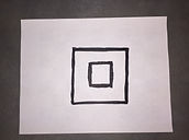
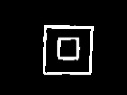
The sole digital input to our project was an image of a piece of paper containing a line drawing. The first step was to eliminate all information from the image except for the line drawing. We ran a prebuilt Canny edge detection algorithm from the Python OpenCV library. From the list of image contours, we chose the contour containing the largest area which was also rectangular. Assuming that the paper reasonably dominated the image, this contour is the outline of the paper. From this contour we can extract the four corners of the paper and then manipulate the image to obtain a top-down view of the paper, cropping all parts of the image beyond the edges of the paper.
Next, we convert the image to grayscale, so that every pixel is an intensity scalar from 0 to 255, We apply a Gaussian blur function (again provided by the OpenCV library) and threshold each pixel at an arbitrary level intensity to classify every pixel as either black or white in order to remove noise from the image. We now have a binary matrix with dimensions approximately 500x700. In order to simplify the path finding process, we decrease the resolution of the matrix by examining blocks of pixels of dimension 5x5. We count the number of black pixels in each, and assign the block a collective 1 or 0 based on whether the ratio of black pixels to white pixels exceeds some threshold percentage (40% in our case).
HARDWARE
SOFTWARE
The software of the finished product had four major consecutive stages: image processing, path planning, Sawyer calibration, and path execution. All executables were written in Python to run on ROS.
Image Processing
The sole digital input to our project was an image of a piece of paper containing a line drawing. The first step was to eliminate all information from the image except for the line drawing. We ran a prebuilt Canny edge detection algorithm from the Python OpenCV library. From the list of image contours, we chose the contour containing the largest area which was also rectangular. Assuming that the paper reasonably dominated the image, this contour is the outline of the paper. From this contour we can extract the four corners of the paper and then manipulate the image to obtain a top-down view of the paper, cropping all parts of the image beyond the edges of the paper.
Next, we convert the image to grayscale, so that every pixel is an intensity scalar from 0 to 255, We apply a Gaussian blur function (again provided by the OpenCV library) and threshold each pixel at an arbitrary level intensity to classify every pixel as either black or white in order to remove noise from the image. We now have a binary matrix with dimensions approximately 500x700. In order to simplify the path finding process, we decrease the resolution of the matrix by examining blocks of pixels of dimension 5x5. We count the number of black pixels in each, and assign the block a collective 1 or 0 based on whether the ratio of black pixels to white pixels exceeds some threshold percentage (40% in our case).

Path Planning
The input to this stage is a binary matrix of dimensions approximately 100x140. The goal is to find a collection of curves (each defined by a series of coordinates in this 100x140 matrix) such that the Sawyer arm moving a pen across the canvas according to these curves would recreate the line drawing. We did not use the Canny algorithm to find these curves because each line corresponds to two edges. Depending on the complexity of the image it is not always clear which two edges correspond to the same line, so an edge merging process is imperfect. Instead, we opted for a simpler greedy algorithm. We treat the input binary matrix as a boolean matrix where each entry indicates whether we have "visited" that particular pixel in our recreation line drawing. All of the entries which are initially 0/false have already been "visited" because we don't want a pen mark there in the final drawing. We scan the binary matrix for an entry that has not been visited yet. The coordinates of that point serve as the starting point of our new curve. We mark that pixel and the pixels in an arbitrary block around it (3x3 in our case) as visited, and then check adjacent pixels to see if any have yet to be visited. If such a pixel exists, then we add its coordinates to the in-progress curve and perform the same visiting process starting from this new point (marking the chunk as visited, looking for unvisited adjacent pixels, and repeating). When we can no longer find any unvisited adjacent pixels, then we check to see if the last point we have added is close to the first point. If it is, then we re-add the first point to the end of the curve, as this curve is likely a closed loop. This algorithm is fairly crude and has much room for improvement, but it served our purposes quite well.
Sawyer Calibration
In order to draw the curves, we need to map the coordinates from our binary matrix (range of 100x140) to 3D coordinates of the destination canvas in the real-world space defined around Sawyer. We positioned our canvas on a horizontal plane in front of Sawyer, and then manually moved the arm to the top-left and bottom-right corners of the canvas, recording the coordinates of these two points. Since we assumed that the canvas was perfectly horizontal, we averaged the Z-coordinates of these two points in order to define the horizontal plane of the destination space. Then, using the two pairs of X and Y coordinates as boundary points, we mapped each binary matrix coordinate to its respective real world coordinate (including the Z-coordinate calculated earlier).

Path Execution
The goal of this stage is to move Sawyer's arm (and attached pen!) through the sets of coordinates derived from the previous three stages so that he will recreate the line drawing on the destination canvas. We assume that when Sawyer's end effector frame is at the z-coordinate determined from the calibration stage and the end effector orientation is orthogonal to the horizontal plane of the canvas, then the pen is in contact with the paper. When Sawyer's arm moves between two points while maintaining this Z coordinate and orthogonal orientation, he will draw the line segment on the canvas which connects the two points. We use the MoveIt package in conjunction with ROS to plan the subpaths between points while simultaneously keeping the end effector orientation constant (and thus the pen perpendicular to the page). Therefore, our path execution algorithm is as follows. Starting from a point above the canvas such that the pen is not in contact with the paper, move to the first point in the curve. We use MoveIt to plan and execute a path to each successive point in the curve. When we have visited each point in the curve, we lift the end effector/pen above the canvas and repeat this process for every curve.